Here’s an alternative title in English:”Metal Furring and Bridging Channel Machine for 1-1/2”×1/2” Carrying Channel, Cu Stud Track, and Purlins”
Description of Bridging / Carrying Channel Roll Forming Machine
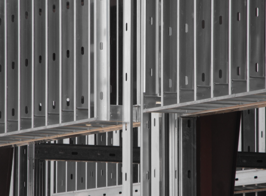
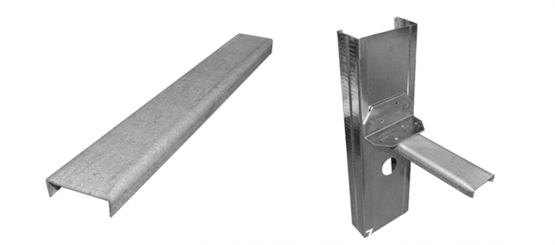
ZTFRM bridging channels serve to reinforce both loadbearing and non-loadbearing steel stud walls and partitions. These channels fit securely into the stud knockout, which helps to improve resistance against twisting forces caused by wind or axial loads. Furthermore, bridging channels are commonly used for drywall ceiling installations, where furring channels are mounted perpendicularly and suspended from the overhead structure. This method offers an effective solution for both strength and stability.
Channel
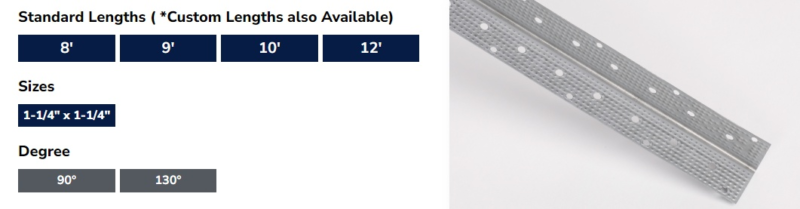
1 ½”×½” Channel×12ft
Bridging channels, often connected to steel studs via clips or welding, provide an efficient solution for preventing stud rotation and bending along the minor axis due to wind and axial forces. These channels are inserted into the stud knockouts and then secured with bridging clips and screws. Typically, lateral bracing is spaced no more than 48 inches apart on center for optimal support.
- Corrosion Resistance:Equipped with a protective galvanized finish.
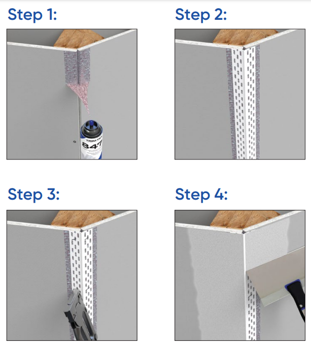
- Ease of Installation: Engineered for straightforward application.
- Adaptability: Compatible with both welding and screw fastening techniques.
- Bracing Needs:Proper bracing of steel stud framing requires the use of bridging clips along with screws. Insufficient attachment of the bridging channel to the steel framing will lead to inadequate bracing.
- Steel Stud Compatibility: Suitable for 3-5/8″, 6″, and 8″ steel studs.
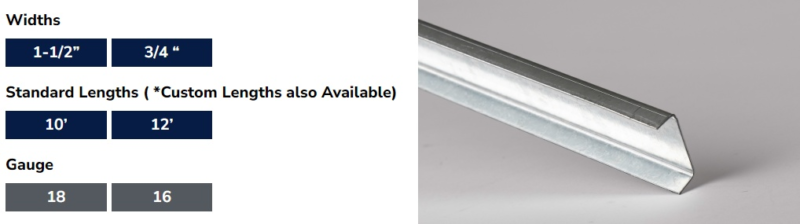
Bridging/Carrying Channel Machine(3/4”×1/2” Channel×12ft) Specification ll
A 3/4” × 1/2” channel, available in 12-foot lengths, is often utilized as a bridging channel and is typically attached to steel studs using clips or welding. This setup helps prevent stud rotation and reduces minor axis bending caused by wind and axial forces. The channel is threaded through stud knockouts and secured with bridging clips and screws. Lateral bracing is generally placed at intervals not exceeding 48 inches on center for stability.
With a galvanized coating to resist corrosion, this channel offers a quick and simple installation process and is compatible with both welding and screw fastening methods. For effective bracing of steel stud framing, bridging clips should always be attached using screws, as proper attachment is necessary for adequate support. This channel is designed for steel studs measuring 1-5/8” and 2-1/2″.
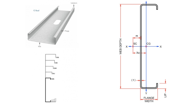
Profile Drawing:
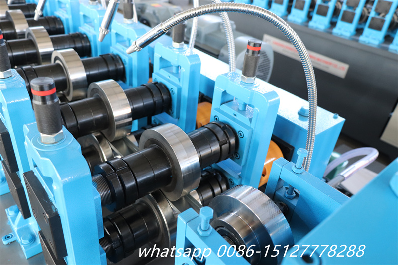
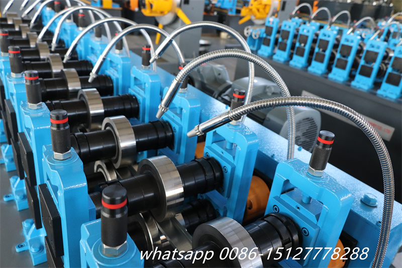
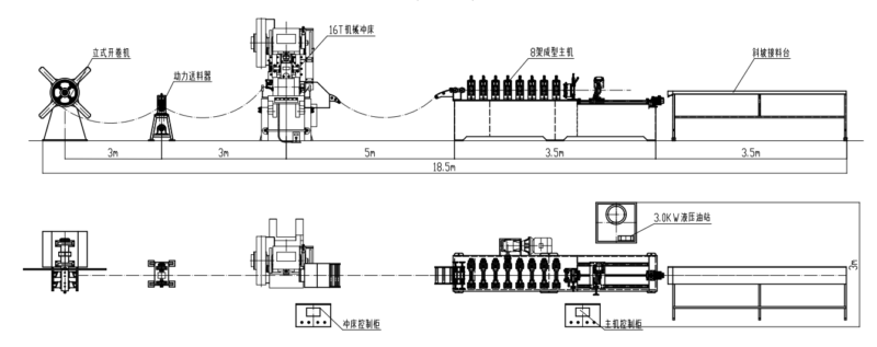
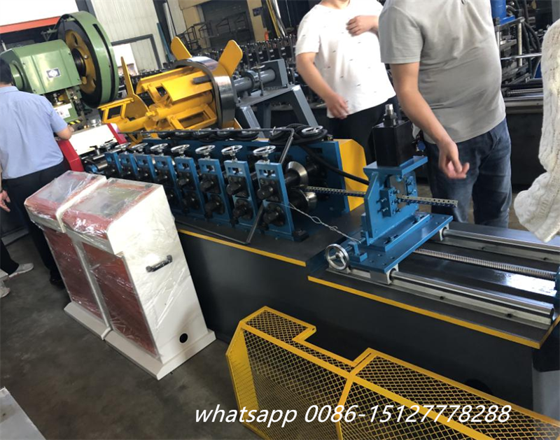
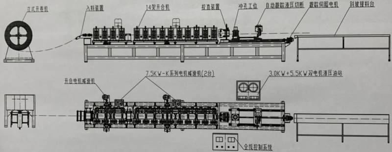
Bridging / Carrying Channel Roll Forming Machine working flow:
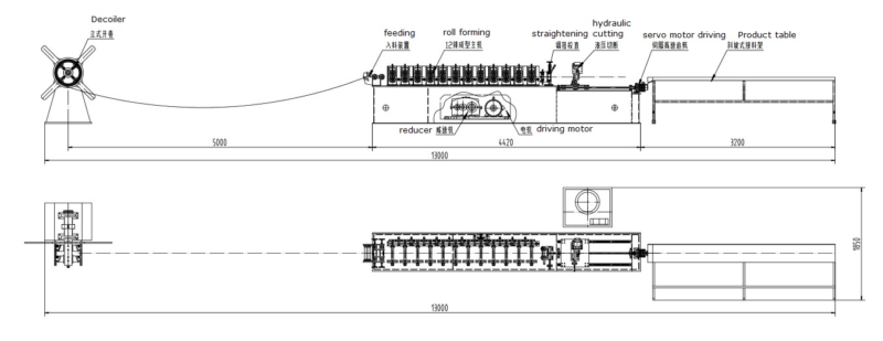
The Technical Specifications Of The Bridging / Carrying Channel Roll Forming Machine:
|
Bridging / Carrying Channel rolling forming machine |
||
| 1.Formed Material | GI | Thickness: 0.4-0.6 mm |
| 2.Decoiler | Hydraulic automatic decoiler | Manual decoiler(will give you as free) |
| 3.Main body | Roller station | 12rows(As your requirement) |
| Diameter of shaft | 45mm solid shaft | |
| Material of rollers | 45# steel, hard chrome plated on the surface | |
| Machine body frame | Metal steel welded | |
| Drive | Gearbox transmission | |
| Dimension(L*W*H) | 5500*800*1200(customize) | |
| Weight | About 3T | |
| 4.Cutter | Automatic | cr12mov material, no scratches, no deformation |
| 5.Power | Motor Power | 7.5KW |
| Hydraulic system power | 5.5KW | |
| 6.Voltage | 380V 50Hz 3Phase | As your requirement |
| 7.Control system | Electric Box | Customized(famous brand) |
| Language | English(Support multiple languages) | |
| PLC | Automatic production of the whole machine. Can set batch, length, quantity, etc. | |
| 18.Forming Speed | 0-50 m/min(customized) | Speed is adjustable according to customer’s request |
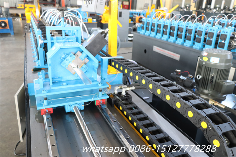
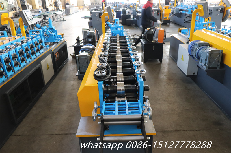
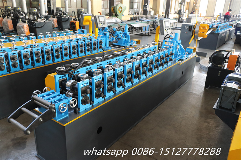
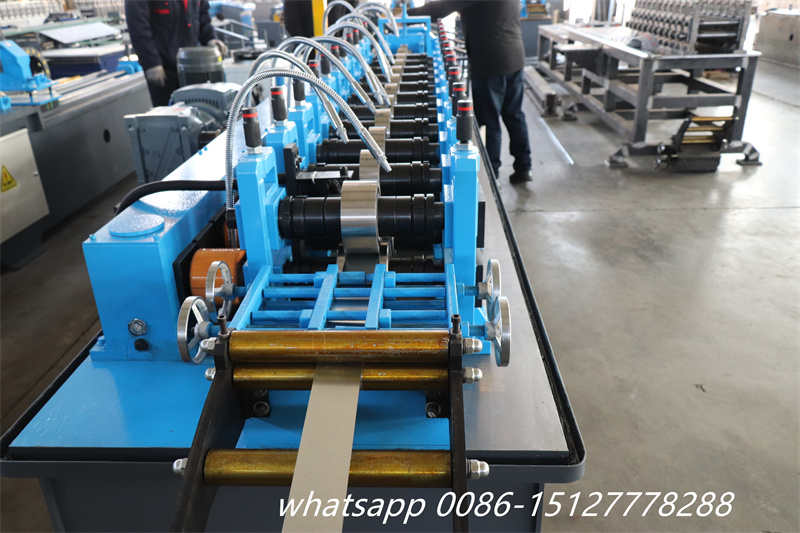
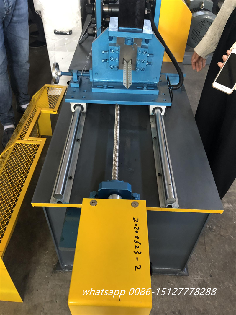
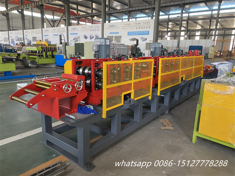
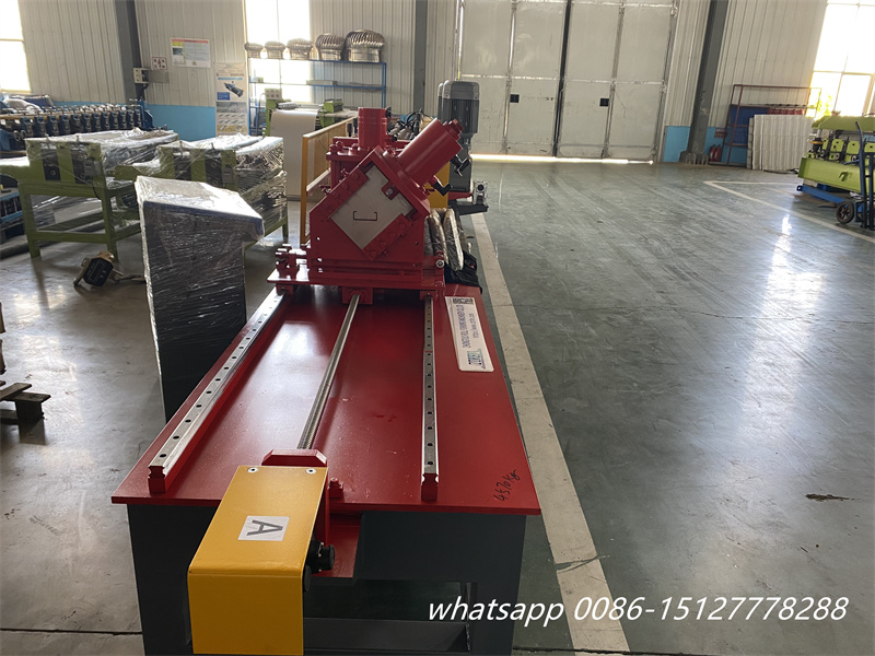
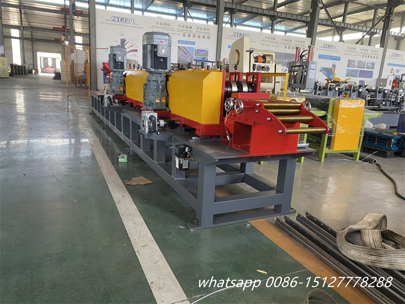
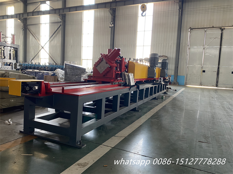
More pictures of the machine: